
Installation instructions Ford mini starters
Q5203, Q5204, Q5205, Q5206, Q5207, Q5501, Q5502, Q5503, Q5504
Remove the old starter motor
- 1. Negative battery cable must be disconnected from the battery before installation.
- 2. Disconnect starter wiring and remove old starter.
Starter installation
- 1. Make sure the mounting surface of the engine block is smooth and free of paint.
- 2. Ford uses two different lengths of starter motors. These very as to how far the starter pinion gear extends past the mounting flange (Figure 3). The pinion gear on cars equipped with automatic transmission extend past the mountain flange by 15,0 mm (Figure 2A). The pinion gear on the starter usually used on manual equipped cars extend 6,0 mm past the mounting flange (Figure 2B).
- 3. Temporary attach the mounting block to the engine. At this point do not bolt the starter to the mounting block. Hold the starter motor temporary up into the position on the mounting block. While holding the starter motor in place, check for clearance between the starter and the engine block and the also exhaust system.
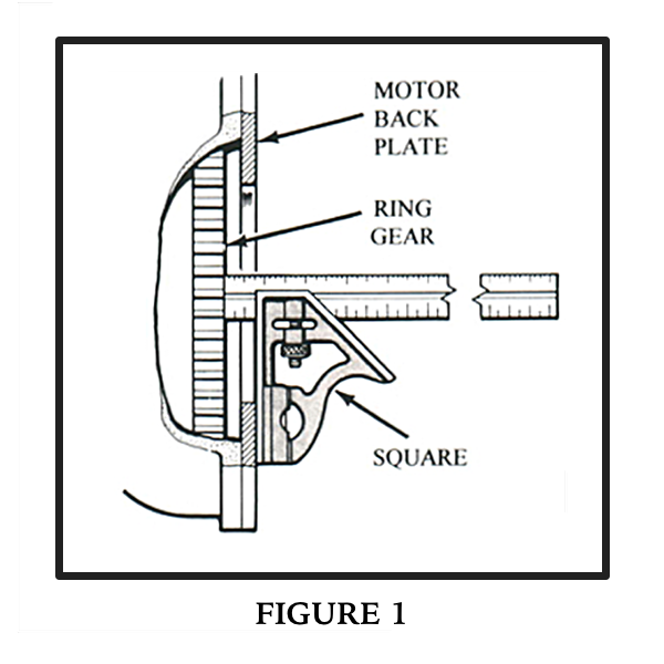
Note there are eighteen pairs of mounting holes located at 20° increments. Rotate the starter until you have roughly equal clearance on both sides of the starter motor. Using a marker pen, make a mark across the mounting block and the body of the starter motor. Remove the starter motor and the mounting block from the engine. Install the two M5 mounting screws into the pair of holes which allow the closest alignment of the previously made marks. Using an Allen wrench, tighten the bolts. - 4. End clearance between the ring gear and the pinion gear teeth in the retracted position is critical. The starter pinion gear to flywheel to ring gear gap should be 1,0-2,5 mm (Fig B) when the pinion is it its relaxed position. This has to be checked in at least 4 positions by manually turning the crankshaft, If not in spec; verify that the ring gear is properly mounted. If the gap is too large or too small, add or remove shims.
The distance from the motor mount plate to the front edge of the ring gear must be measured. (Fig 1), call it A. Now measure the protrusion of the pinion gear (Fig 3), call it B. Subtract A-B, should be 1,0-2,5 mm. Add shim if necessary. Two round 1.5 mm thick circular shims are included in the kit.
Electrical connections
- Fords are equipped with a remote starter solenoid. Your new TORQQ starter is equipped with an internal starter solenoid and we advise to use this and not use the original remote solenoid. Remove the wires from the remote Ford starter solenoid. Install the connector supplied in the kit to the wire that triggers the solenoid and install it to the starter motor. Install the ring connector for the battery connection to the starter motor.
- Make sure that the battery is in good condition. Also the terminals to the battery need to be inspected. If the battery is placed far from the starter motor, pay attention to voltage drop.
- Install the battery cables and enjoy the powerful TORQQ starter.